
Standalone Capacitive Touch Panels — Custom CTP Without a Display
Some products already have a display and only need the touch layer. Others need a front panel that senses input without showing an image at all. This page is about that part on its own: a projected-capacitive (PCAP) touch panel supplied without an LCD cell, backlight or display driver board. We build the cover lens, sensor, controller and flex tail to your mechanical outline, then validate the stack against the surface it will actually be used behind.
If you are looking for a display module that already includes touch, see the standard catalog instead. Everything below concerns the touch assembly as a separate custom part.
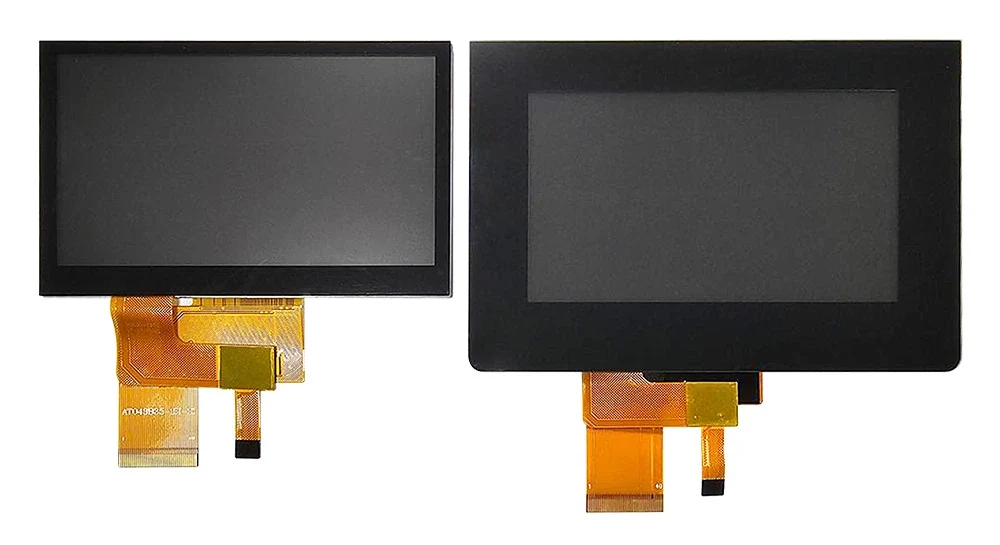
What a Standalone Touch Panel Contains
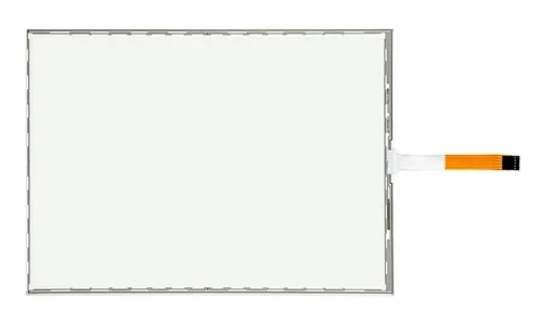
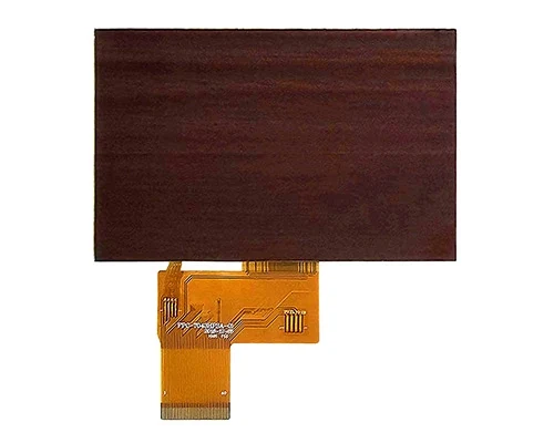
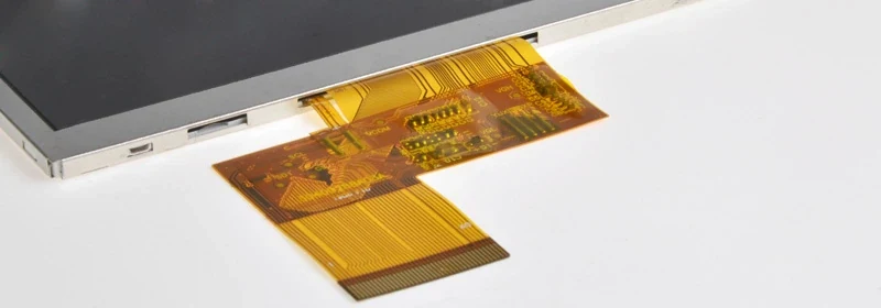
A standalone assembly is built as a stack: cover lens, transparent sensor, bonding layer, and the controller with its flex tail. The illustration shows the sensor glass and FPC on their own, with no LCD cell behind them.
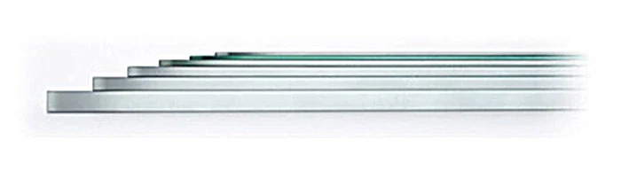
A PCAP touch assembly is a stack, not a single sheet. Understanding the four layers makes the specification conversation much shorter:
| Layer | What it does |
|---|---|
| Cover lens | The user-facing glass or film: outline, thickness, printing, cut-outs and surface finish |
| Touch sensor | The transparent electrode pattern that senses the change in capacitance |
| Bonding layer | OCA optical bonding or air bonding between lens, sensor and the host surface |
| Controller + FPC | The touch IC, its firmware, and the flex tail that carries power and the host interface |
There is deliberately no LCD in that list. The assembly is a front-surface input device; whatever sits behind it — a display you already source, a printed graphic, or nothing at all — remains your choice.
What Can Be Customised
| Item | Options discussed at project start |
|---|---|
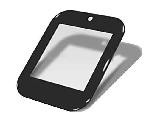
| Outline & active area | Rectangular, round, cut-corner or shaped; sensor area matched to your drawing |
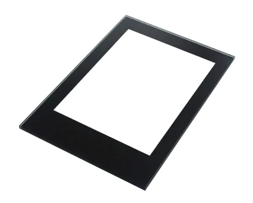
| Cover lens | Glass thickness, CNC edge, chamfer, silk printing, logo window, holes and cut-outs |
| Sensor structure | Glass- or film-based sensor constructions selected for thickness, optics and environment |
| FPC tail | Exit position, tail length, connector type and stiffener to reach your main board |
| Controller & firmware | Host interface and sensing configuration tuned to the final lens and use case |
| Bonding | OCA optical bonding or air bonding to the lens or to your own front surface |
| Surface finish | Anti-glare, anti-reflection and anti-fingerprint treatments |
| Mounting | Gasket, adhesive frame or bracket approach for sealing into the enclosure |
None of these are fixed catalog values. Each is confirmed per project after the drawing and the operating environment are known, which is why we ask for both up front.
Integrating With a Display You Already Buy
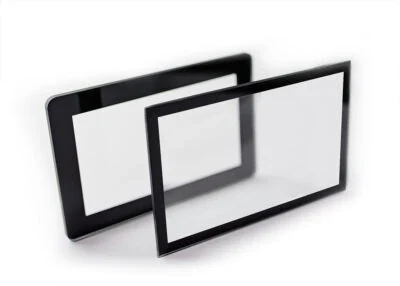
The lens outline is taken from the bezel drawing and the sensor active area is aligned to the viewing area of the display you already source. The display itself stays untouched; only the front input layer is built.
The most common request is a touch panel built to sit on a display the customer already has. What matters is not the diagonal size alone but the active-area position, the bezel opening, the stack height available inside the enclosure, and where the flex tail can physically escape. We align the sensor active area to the display's viewing area, set the lens outline to the bezel drawing, and route the FPC so it does not cross a mounting boss or a gasket line.
Optical bonding to the display is one option; leaving an air gap is another. The trade-off is optical performance versus reworkability and mechanical tolerance, and our air-vs-optical-bonding guide covers it in detail. Either way, the touch controller is configured against the final stack, not a bare sensor, because lens thickness and coating change the sensing baseline.
Controller, Firmware and Host Interface
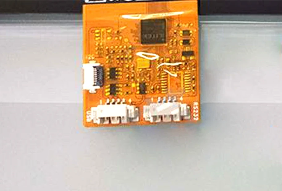
The controller and firmware are configured against the final stack. Host interface, report format and noise tuning are set during sample validation rather than assumed from a fixed list.
The controller is where a touch panel either feels right or frustrates the user. I2C and USB HID are the usual starting points for embedded and host-based systems; the report format, touch-point count and power behaviour are set to match the host driver and the application. Firmware also carries the tuning for the environment: glove operation, water rejection, hover suppression and the noise floor near switching power supplies or wireless modules.
EMC and ESD behaviour belongs in the same conversation. Industrial equipment often puts a long flex tail next to a motor drive or a radio, so grounding, shielding and the controller's noise immunity are reviewed with the enclosure layout before samples are built. This is engineering configuration, not a claim of a fixed immunity figure — the test plan is agreed per project.
Cover Lens and Surface Treatment
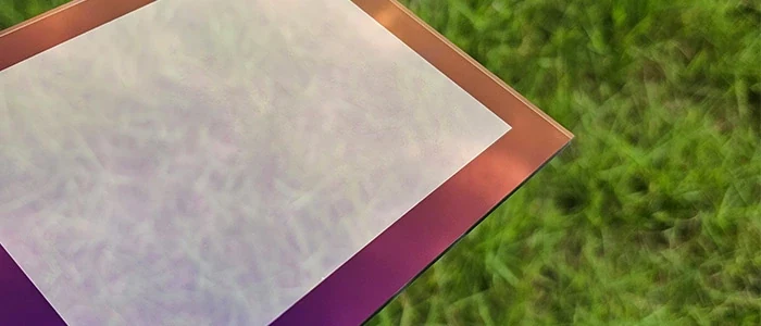
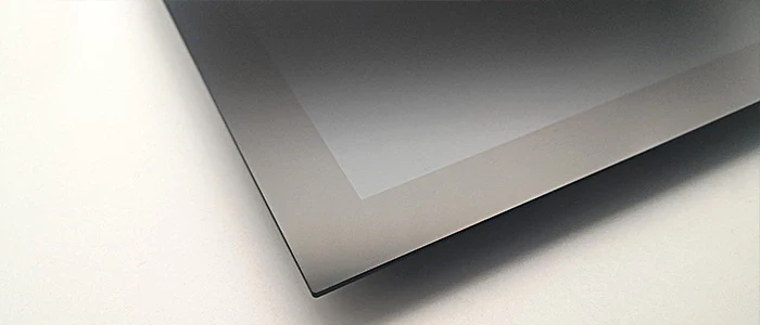
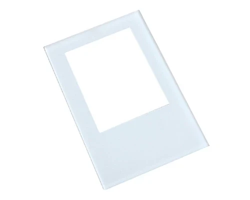
The lens defines both the look and the durability of the front surface. Anti-glare etching softens reflections in bright indoor lighting, anti-reflection coating improves contrast where light is strong, and an anti-fingerprint layer makes shared equipment easier to keep clean. Thickness, edge geometry, printed borders and window placement are all set from the mechanical drawing. Our custom cover glass page covers the coating and bonding choices in more depth.
From Drawing to Samples
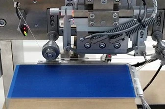
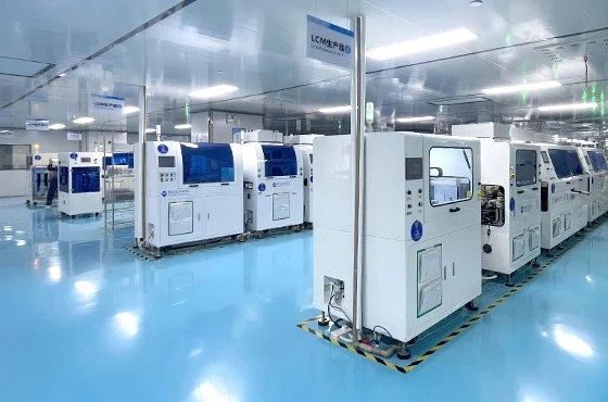
A typical project starts with an outline drawing, the display model or active-area dimensions, the host interface and the environment the panel must survive. We turn those into a stack proposal and a drawing for approval, then build samples for mechanical fit, optical check and touch tuning. Sample lead time is quoted in weeks and confirmed per project; volume scheduling follows the approved sample. Long-term availability is planned on a 5+ year supply horizon so the panel does not become the part that forces a redesign.
Who This Service Is For
This is an OEM engineering service for equipment manufacturers integrating a front panel, for distributors assembling a bundled solution for their customers, and for design engineers who need a touch layer that matches an existing mechanical design. It is not a repair or replacement service for consumer devices, and it is not a drop-in universal touch film — every panel is built to a specific outline and stack.
Related Guides
- Custom Cover Glass & Lens Solutions — lens shape, coating and bonding
- Air Bonding vs Optical Bonding — choosing the stack
- Capacitive vs Resistive Touch Panels — technology choice
- CTP Manufacturing Process — how the sensor and lens are built
- Custom Displays — when a complete module is the better route
Frequently Asked Questions
Do you supply a display with the touch panel?
No. A standalone touch panel is supplied as the cover lens, sensor, controller and FPC only — no LCD cell, no backlight and no display driver board. If you need a complete display assembly with touch already bonded, our standard TFT modules with PCAP are listed separately in the product catalog.
Can the panel be made to fit a display we already buy?
Yes, provided we have the outline drawing, active-area position and the mechanical stack. The lens shape, sensor size, FPC exit and controller configuration are then matched to that display and confirmed per project before tooling.
Which host interfaces can be supported?
I2C and USB HID are the usual starting points for projected-capacitive touch, with the controller and firmware chosen to suit the host. Interface, report format and touch-point count are all confirmed per project rather than assumed from a fixed list.
Can the touch work with gloves, water or a thick cover lens?
These are firmware and stack-tuning questions. A thicker lens, gloved operation and water on the front surface each change the sensing baseline, so the controller is configured against the final lens and the real operating environment during sample validation.
What do you need to prepare a proposal?
A mechanical outline drawing, the display model or active-area dimensions, the required lens finish, the host interface, the operating environment, and the quantity you plan to build. Long-term availability is planned on a 5+ year supply horizon, and sample lead time is quoted in weeks.
Talk to Our Engineers
Send the outline drawing, display or active-area dimensions, host interface and operating environment to sales@odmlcd.com. We will reply with a stack proposal, the interface it implies, and the information needed to move to samples.