
Capacitive Touch Screen Modules (CTP) — Integration Overview
RONEN's capacitive touch screen modules pair industrial TFT LCD panels with projected-capacitive (CTP) touch, available with air or optical bonding and controllers such as GT911, ST1633i and ILI2511. Select a standard touch module below or ask our engineers to integrate touch into your standard design.
- 31 standard TFT modules with built-in capacitive (CTP) touch
- Air bonding or optical bonding; cover-lens standard range available
- Controllers: GT911, ST1633i, ILI2511 and more
- Multi-touch HMI for industrial, medical and outdoor equipment
35 standard models in this family
One Assembly, Two Jobs: Display and Touch
A capacitive touch screen module is a complete display assembly. An industrial TFT LCD cell and its backlight sit behind a projected-capacitive (PCAP) sensor, a cover lens and a controller board, all delivered as one mechanically matched part with a flex tail for the host. The module shows the image and senses the touch.
That is different from a standalone touch panel, which is the touch layer supplied without any LCD. Every model in the grid below includes its display. If your design already sources a display and you need only the touch layer, see standalone capacitive touch panels without an LCD.
- 35 standard PCAP display modules, from 3.5 to 15.6 inches
- TN and IPS panels with RGB, LVDS and MIPI display interfaces
- Touch bridged to USB, I2C or UART on the host side
- Air or optical bonding, cover lens and flex exit defined at design-in
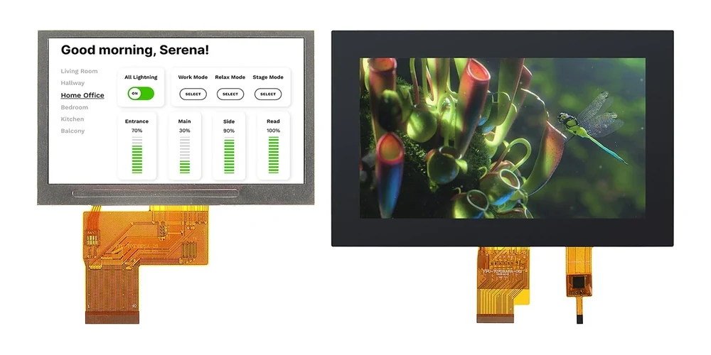
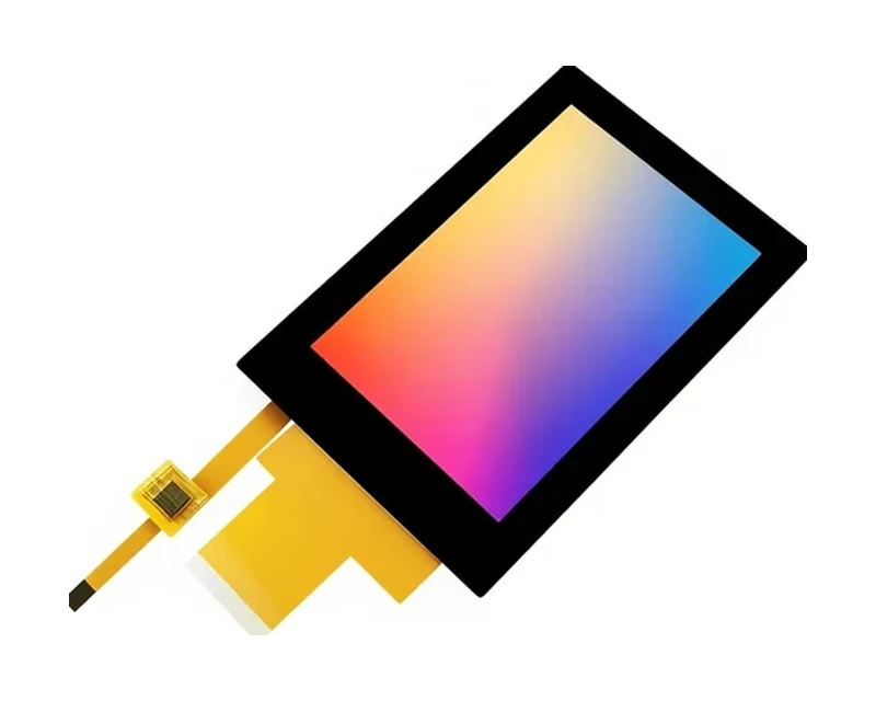
RG-T035QHI-03CP
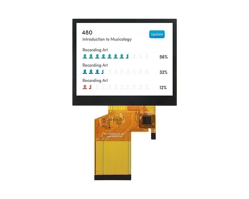
RG-T035GLH-01CA
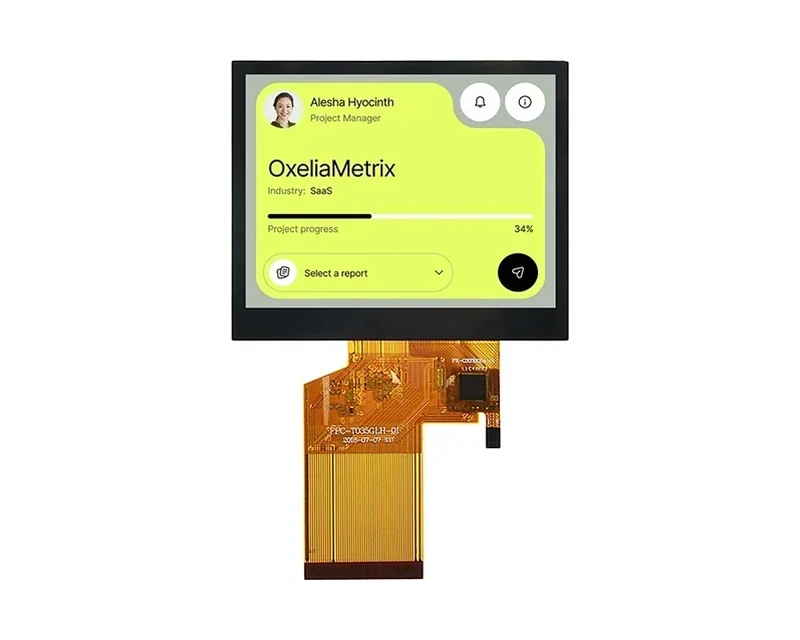
RG-T035GLH-02CA
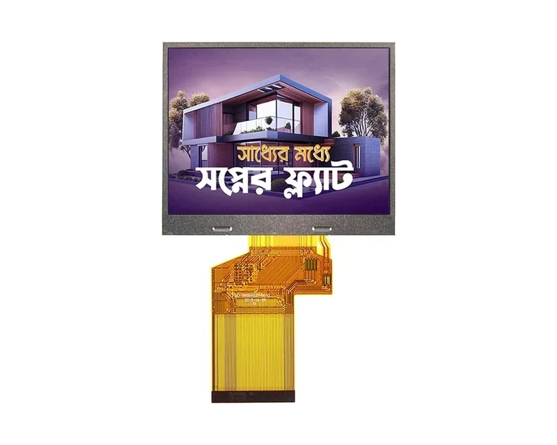
RG-T035HLS-01CP
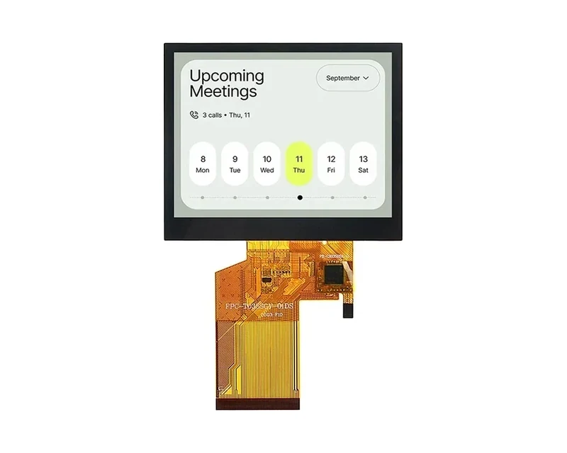
RG-T035SGV-01CP
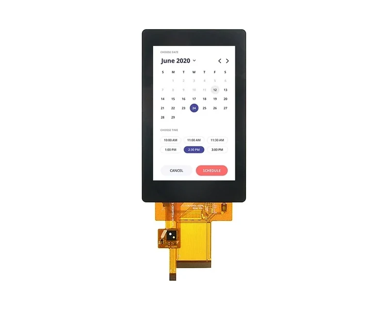
RG-T0397BVSA-02CP
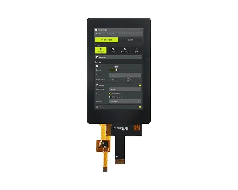
RG-T0397BVSA-01CP
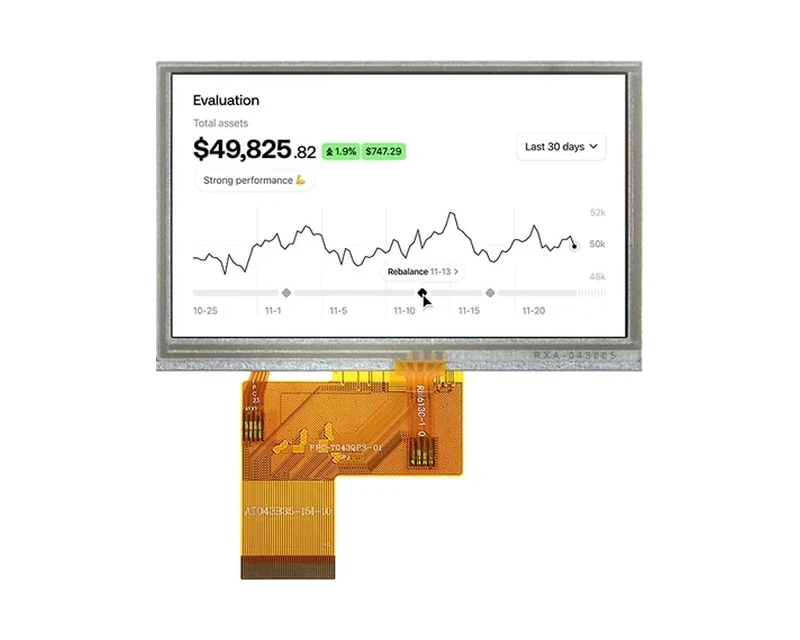
RG-T043QPS-02CA
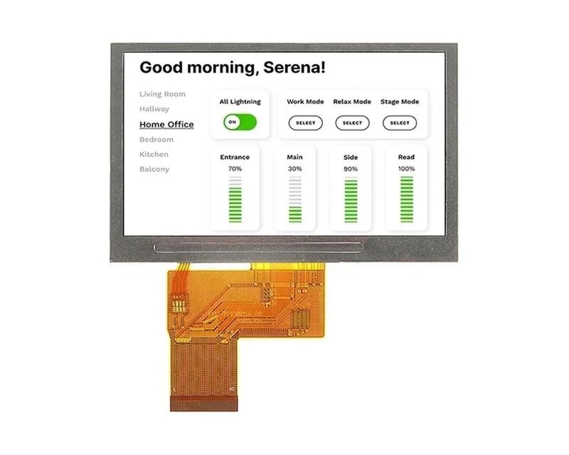
RG-T043BPSA-01CA
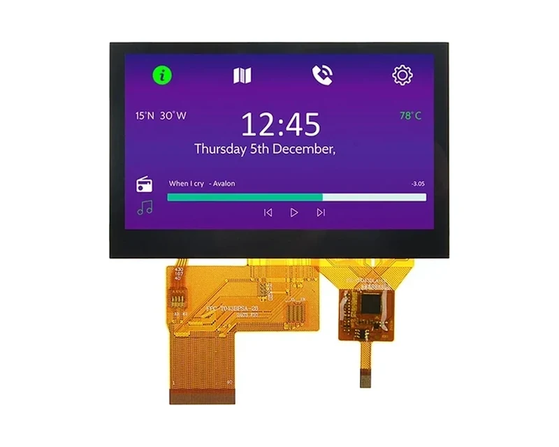
RG-T043BPSA-02CP
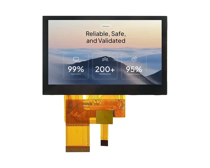
RG-T043BWSA-02CP
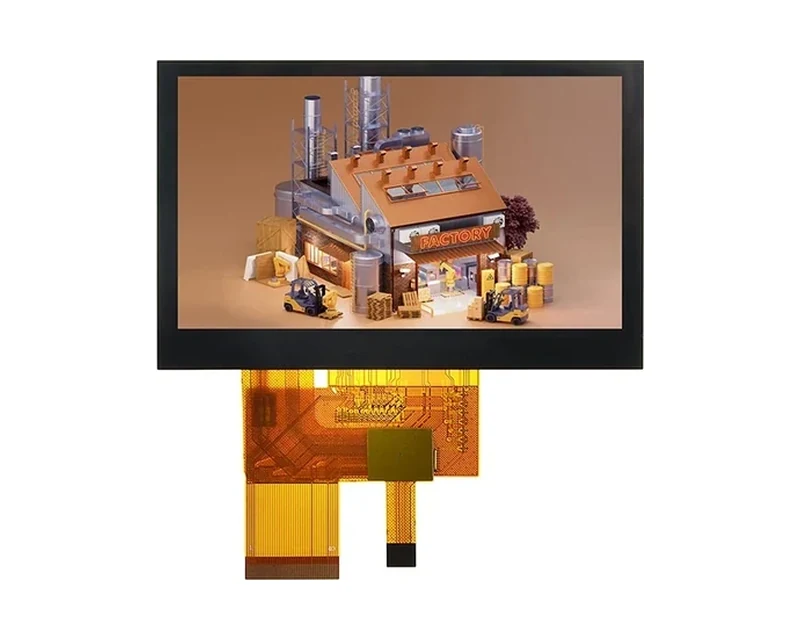
RG-T043BWSA-28CP
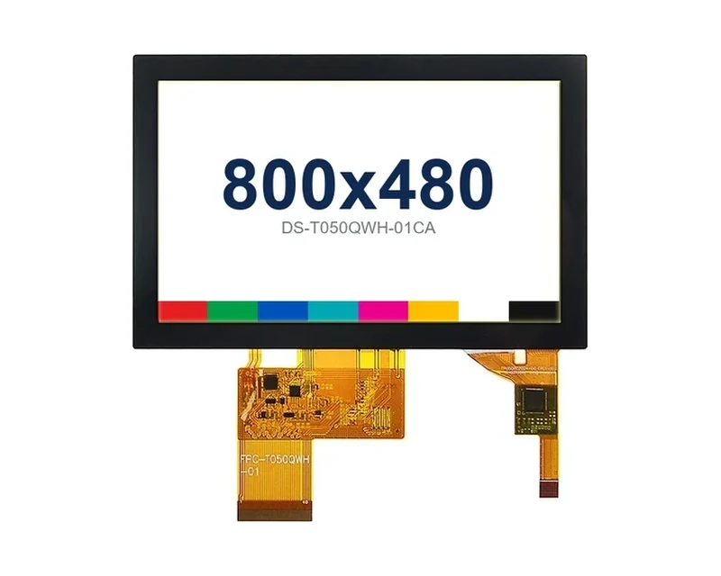
RG-T050QWH-01CA
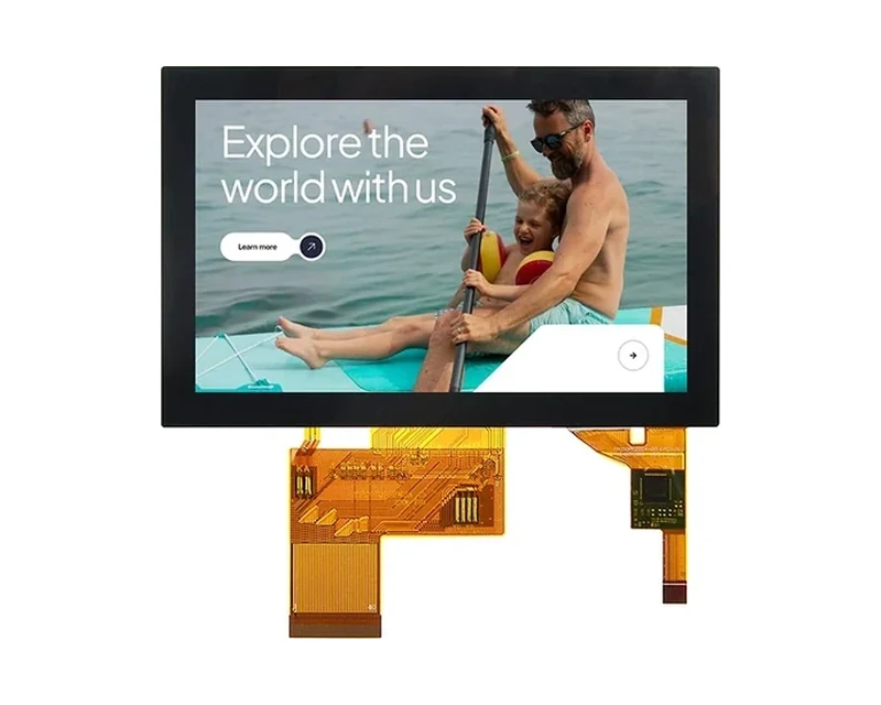
RG-T050BWSA-30CP
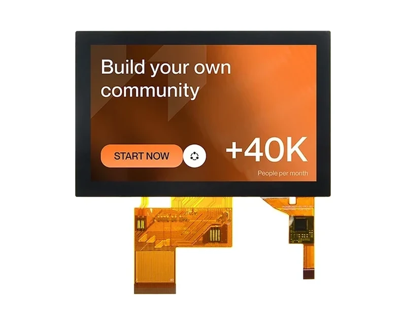
RG-T050BWSA-02CP
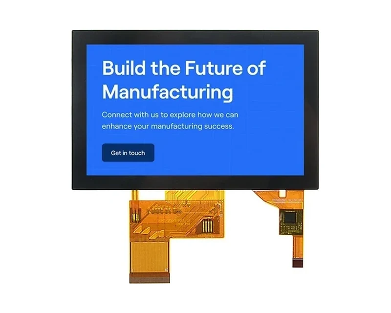
RG-T050BWSWA-02CP
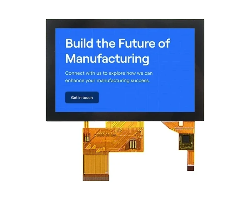
RG-T050BWSWA-02CA
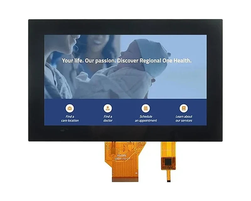
RG-T070QWE-01AD
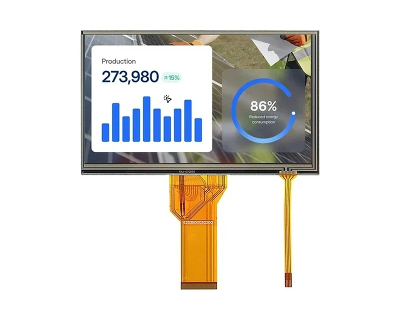
RG-T070QWHW-01CA
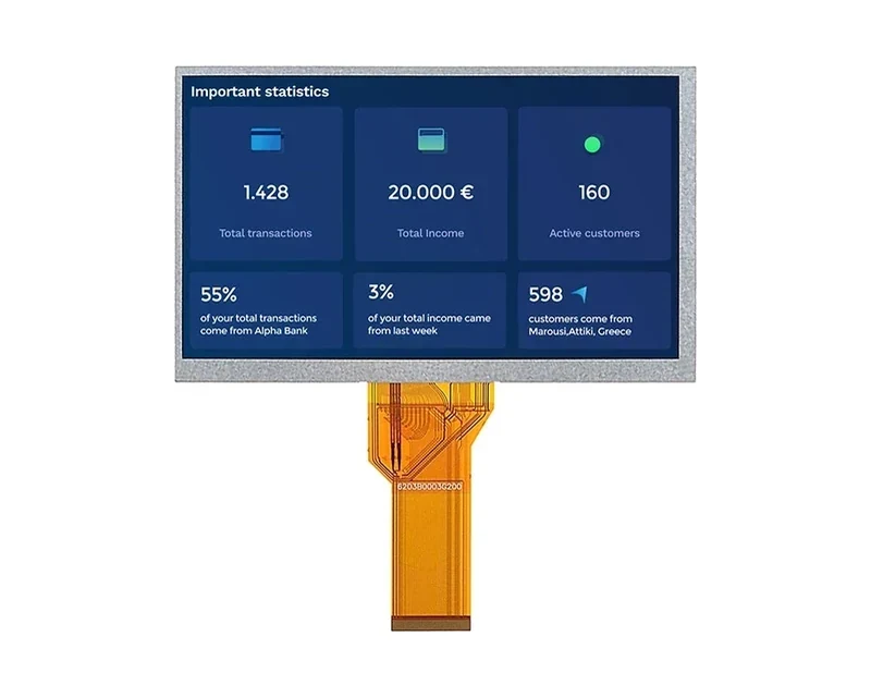
RG-T070QWHW-02
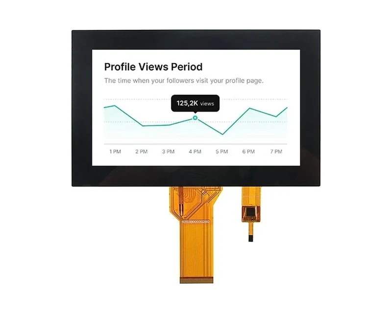
RG-T070QWHW-02CA
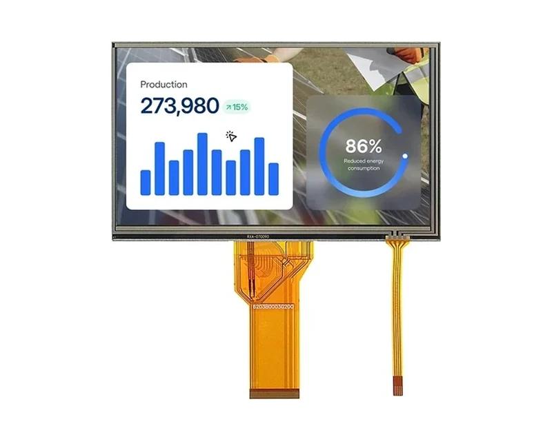
RG-T070QWHW-03CA
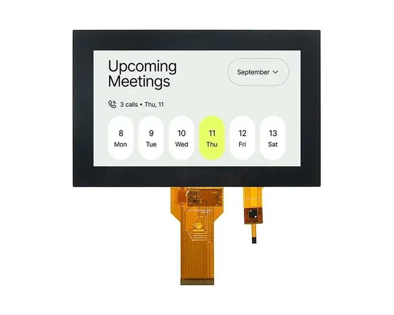
RG-T070KWSA-01CA
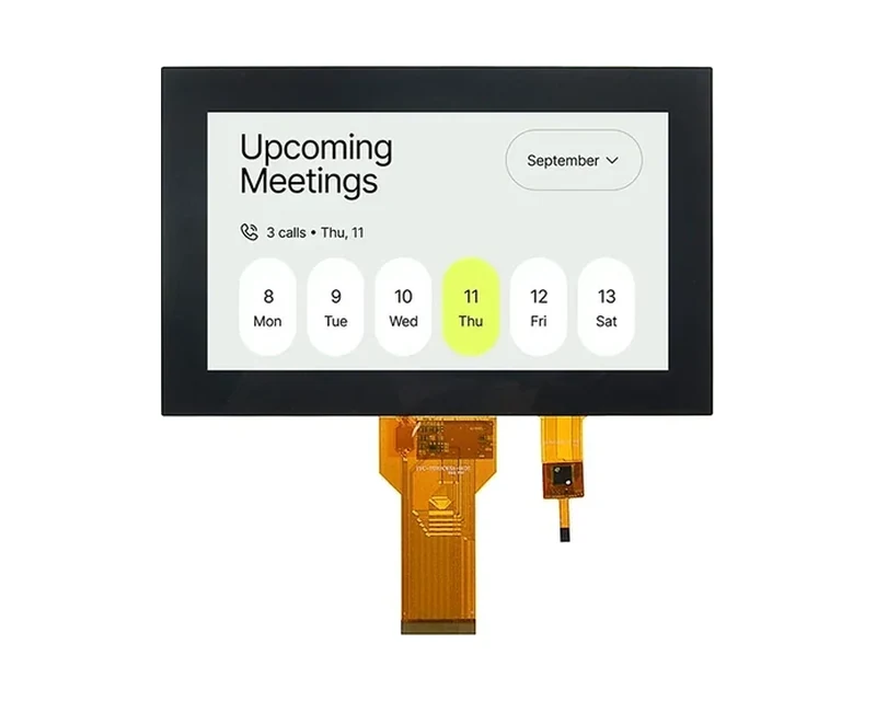
RG-T070KWSA-01CP
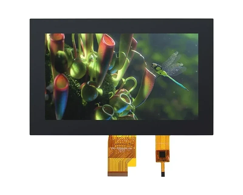
RG-T070BAHA-01CA
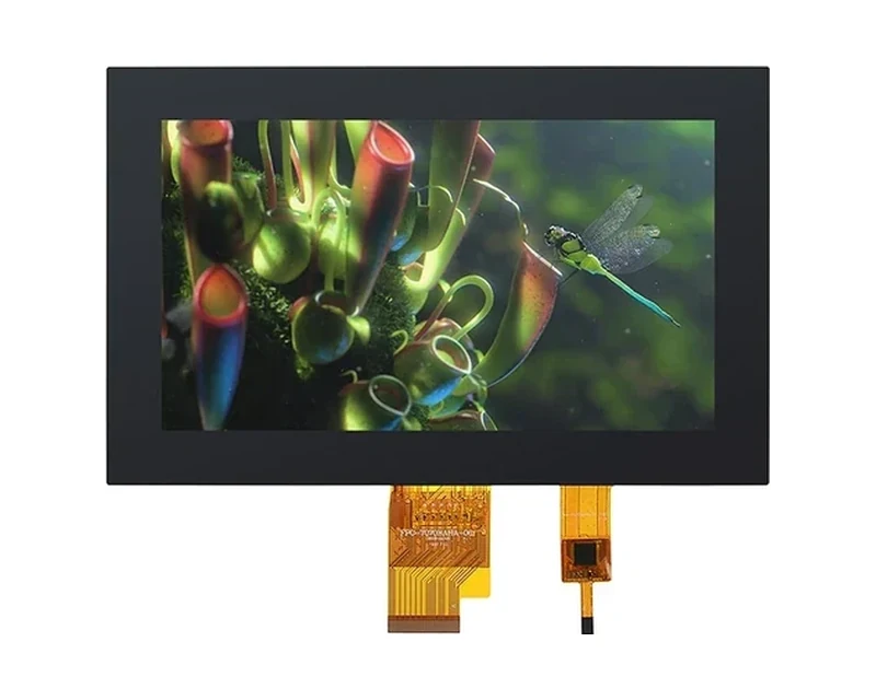
RG-T070BAHA-01CP
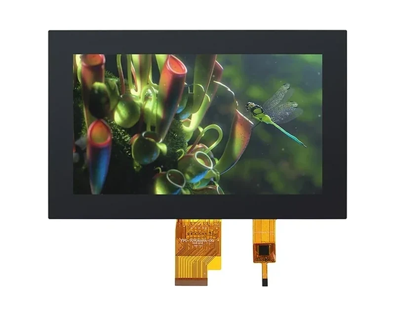
RG-T070BAHA-03CA
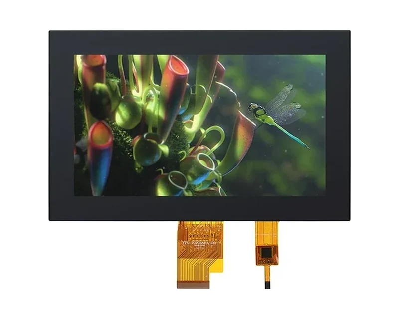
RG-T070BAHA-03CP
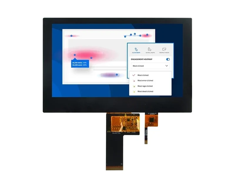
RG-T070BAHA-19CA
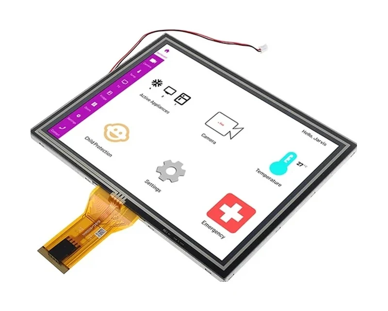
RG-T080BXEA-01CP

RG-T101BAHA-02CP
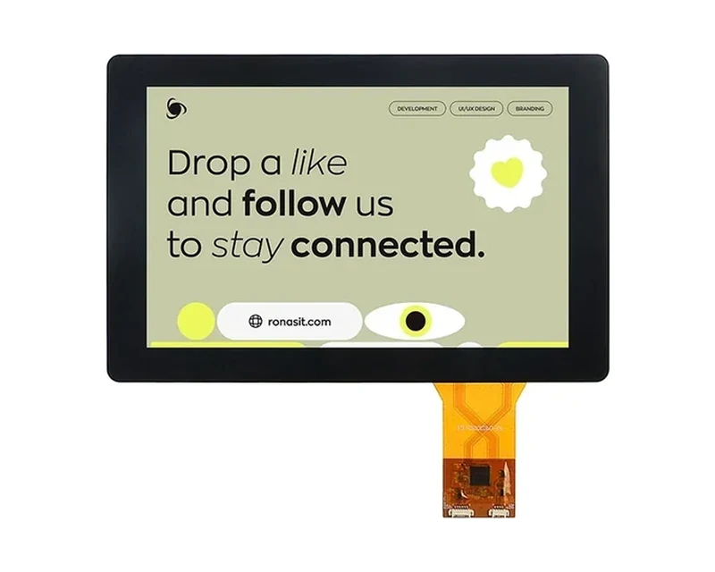
RG-T101HIEWA-01CP
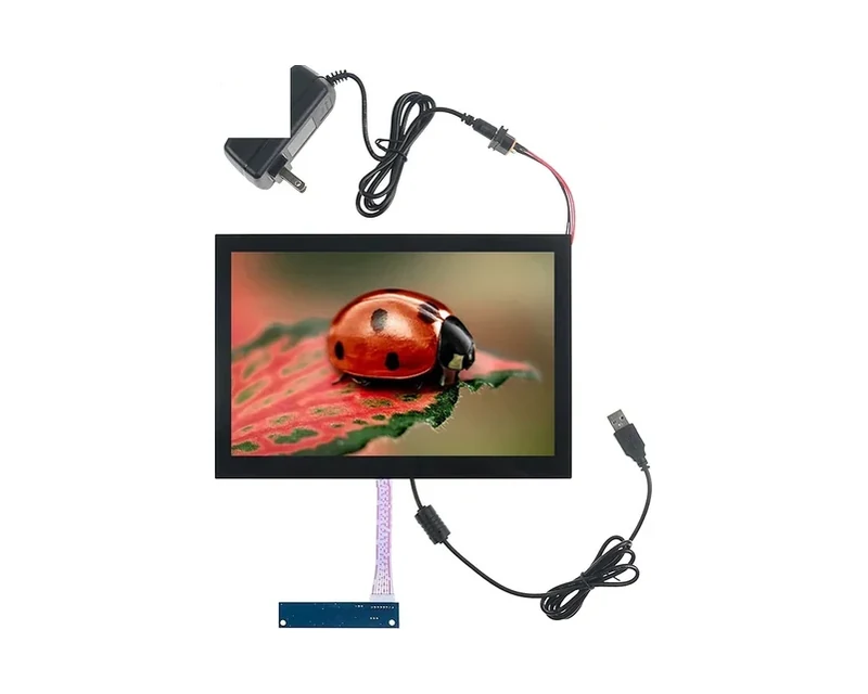
RG-T101QIHA-01CA-B
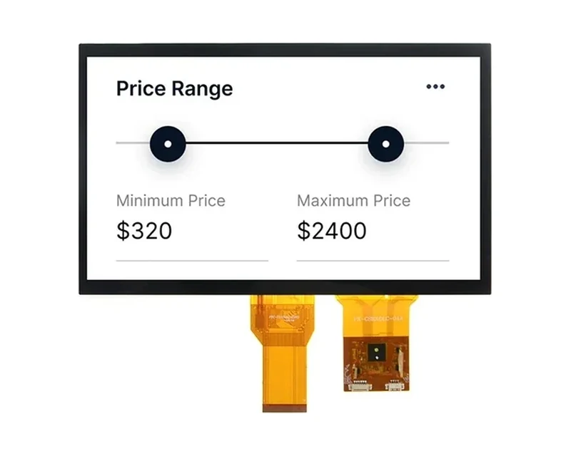
RG-T101BAHA-02CD
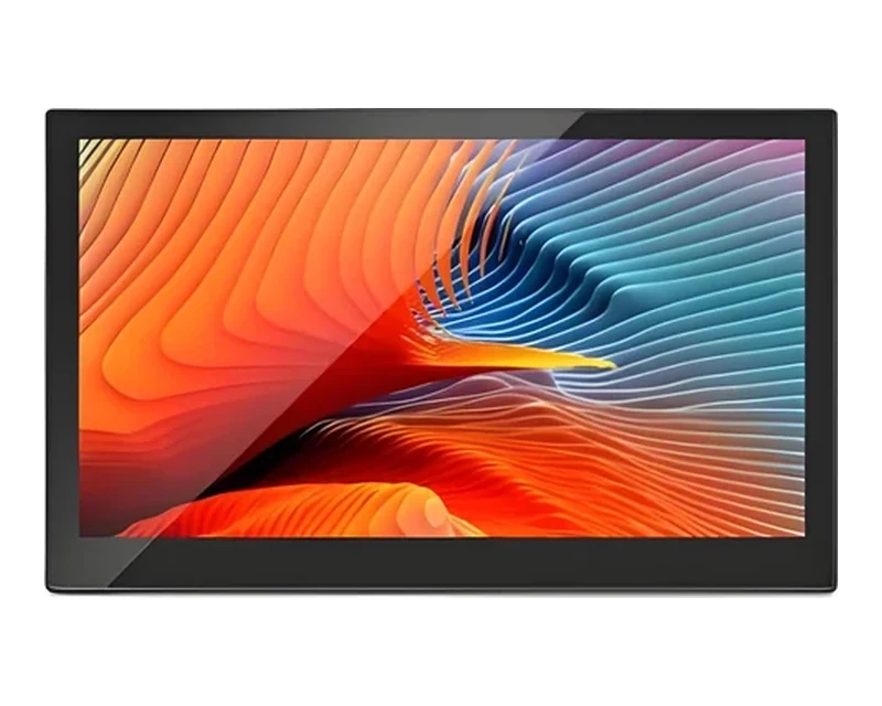
RG-T156BFHWA-02CP
Can’t find the exact model you need?
This is a standard model, and our online catalog shows only part of what we build. We hold additional models not listed here, and we can adjust brightness, interface, touch or outline within an existing product family, or evaluate a fully custom solution. If this model does not fully match your requirements, please email your specifications to sales@odmlcd.com. We’ll help you identify the right part or assess a custom option.
What Is Inside a CTP Display Module
Specifying a touch display is easier once the stack is explicit. Four layers do the work, and a change to any one of them ripples into the others — which is why we ask for the mechanical drawing and the host interface together rather than one at a time.
| Layer | What it does | What is fixed at design-in |
|---|---|---|
| Cover lens | Front glass with printed border, cut-outs and surface treatment; the only layer the operator touches. | Shape, thickness, printing and coating are set with the mechanical drawing. |
| Touch sensor | Projected-capacitive transparent electrode layer that reports touch coordinates. | Sensor stack and channel layout are matched to the cover lens and the host controller. |
| LCD cell | The TFT panel that forms the image; the reason this product is a display module. | Resolution, viewing angle and luminance come from the selected standard model. |
| Backlight and driver | LED backlight, display driver and the flex tails that carry both display and touch signals. | Interface and firmware load are agreed before the first sample build. |
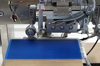
The bonding step is where the stack becomes one part. Our engineers match the adhesive, the cover lens and the sensor to the display you select, then validate the assembly against the environmental targets of the equipment it will be built into.
For a deeper look at the trade-offs, read air bonding vs optical bonding and the CTP manufacturing process.
Air Bonding or Optical Bonding
Both constructions are available on this product line. The choice changes optical performance, mechanical stiffness and how the front of the equipment is assembled; it is one of the first decisions we settle with OEM engineering teams.
| Air bonding | Optical bonding | |
|---|---|---|
| Construction | Sensor attached around the perimeter, with an air gap over the active area. | Sensor fully laminated to the display or cover lens with optically clear adhesive. |
| Optical behaviour | Two extra reflective surfaces inside the stack. | Fewer internal reflections, so contrast and sunlight readability improve. |
| Mechanical behaviour | Simpler stack, easier to rework during prototyping. | Stiffer assembly with better resistance to shock and vibration. |
| Typical use | Cost-sensitive indoor equipment and early prototypes. | Outdoor, high-brightness, medical and vehicle-mounted equipment. |
| What we need from you | Outline drawing, display model and cover lens specification. | The same inputs plus the required optical stack and environmental targets. |
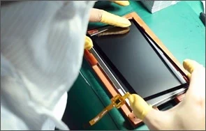
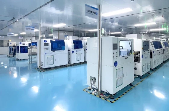
From Sensor Glass to a Tested Module
Touch modules are built in a cleanroom and verified as a complete assembly: the display is driven, the touch grid is exercised, and the bonded stack is inspected before packing. The photographs below are from our own production floor.
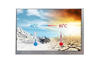
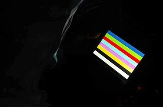
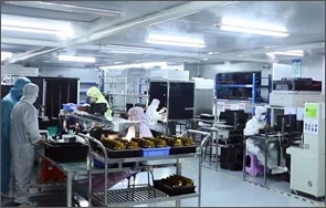
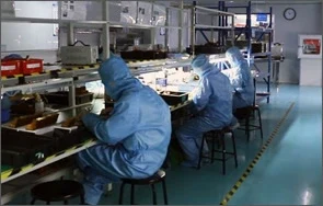
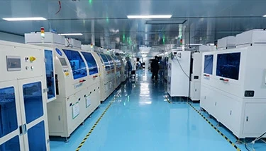
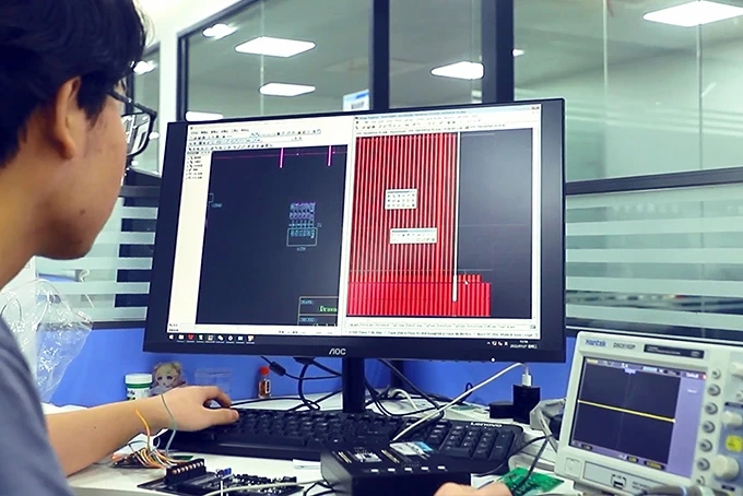
Before a build is released, the team checks the cover lens fit, the flex exit, the controller firmware and the touch report format against the host. That handoff is documented in customisation FAQ and in the display adapter board guidance.
Controllers are selected for industrial EMI environments and tuned for the actual cover-lens thickness, so touch behaviour stays stable once the module is inside a metal housing or behind a thick front glass.
Choose by Screen Size
The 35 standard models below are grouped by diagonal size. Pick the size and resolution that fit the enclosure first, then settle the touch stack, cover lens and host interface. Every link opens an existing standard model page with its own specification table and enquiry form — there is no separate touch-only catalog to cross-reference.
Integration Checklist for OEM Engineers
Six inputs let us quote and build the right module the first time. Having them ready shortens the sample cycle by weeks.
- Mechanical outline — active area, cover lens size, corner radius, cut-outs and mounting holes.
- Display choice — diagonal, resolution, TN or IPS, luminance and viewing direction.
- Display interface — RGB, LVDS or MIPI, plus the pinout of the host board.
- Touch interface — USB, I2C or UART, and the driver environment on the host.
- Bonding and surface — air or optical bonding, AR / AG / AF treatment, cover lens thickness.
- Environment — operating temperature, glove or wet-hand use, EMI and cleaning agents.
Related engineering guides: custom cover glass and lens, capacitive vs resistive touch, custom cable assembly and custom display projects.
Supply Continuity and Project Terms
Standard models in this family are held in stock for OEM and distributor projects, with a 5+ year supply continuity commitment on the line. Order quantities are agreed per project, and sample and production schedules are confirmed in weeks at design-in. If a standard model does not match the outline, the same cover lens, bonding and firmware work can be applied as a custom project without changing display supplier.
Interface & driver options
Every CTP module above ships with an FPC tail: the TFT side on the panel's native interface, the touch side on I2C. If your host board does not speak that natively, we can supply a matching driver board so the module plugs straight in:
- RGB / LVDS — standard TTL-parallel or LVDS driver boards, designed and built in-house.
- MCU (8080 / SPI / I2C) — for resource-limited controllers; initialization code included.
- UART / RS-232 / RS-485 — serial command interface for quick integration.
- HDMI / VGA — plug-and-play kits for kiosks, prototypes and field service.
Touch is bridged to the host port (USB / I2C / UART depending on the design) on the same PCBA, so panel and touch arrive pre-matched. Driver options are quoted per project — send your host interface and we will propose a board.
See also: Display Driver Board & PCBA · HDMI / VGA display kits · MCU-interface modules · UART / serial displays · Custom Displays overview
FAQ
Is the touch responsive?
Our PCAP line (35 standard models) supports 10-point multi-touch, glove and wet-hand operation, with ≥100 Hz sampling rate. Controllers are selected for industrial EMI environments and can be tuned for the thickness / cover-lens stack-up.